

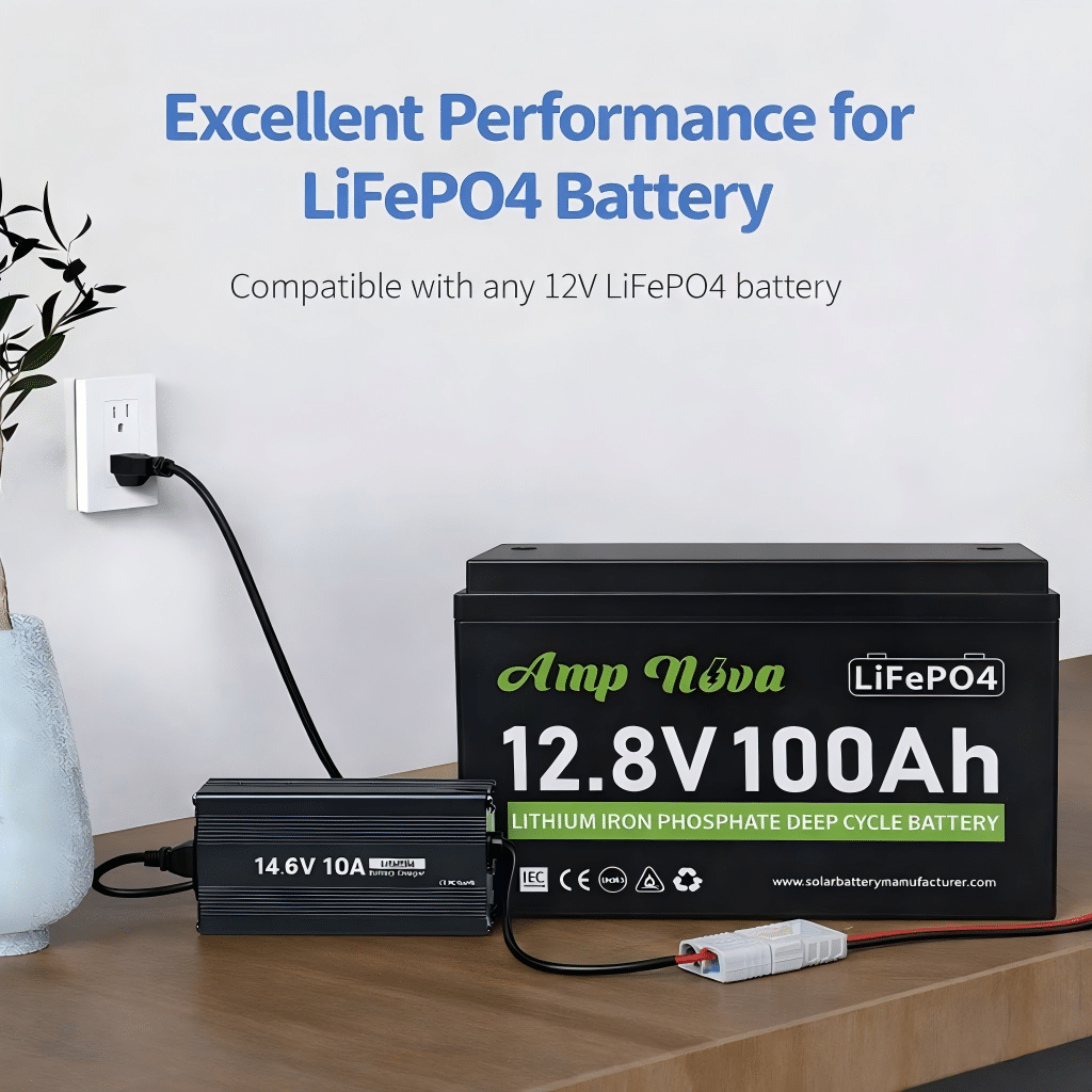
how to charge lifepo4 battery?
I see charging mistakes on our test benches all the time, and most failures start with one thing: someone used a lead-acid profile or the wrong voltage for the pack.
To charge a LiFePO4 battery safely, use a LiFePO4-compatible CC/CV charger, confirm whether the pack is 12V/24V/48V, then set absorption near 3.45–3.65V per cell and a reasonable current (often 0.2C–0.5C). Avoid lead-acid modes like equalize/desulfate, and do not charge below 0°C unless the battery is heated or rated for it.
In this guide, I will show the settings we use in QC, how to verify them with a meter, and how to fix the most common BMS-related charging problems.
Choose the Right Charger for a LiFePO4 Battery
On our production line, we can usually tell within minutes when a battery was charged with a lead-acid algorithm because the BMS logs show protect events and the pack never looks “calm.”
Choose a charger with a true LiFePO4 (LFP) profile or fully adjustable CC/CV settings, and confirm the charger voltage matches your battery (12V/24V/48V). Avoid lead-acid features like equalization and desulfation, because they can push voltage too high and trigger BMS cutoff or shorten battery life.
Why LiFePO4 chargers are not the same as lead-acid chargers
LiFePO4 chemistry behaves differently from lead-acid:
- Voltage curve is flatter. State of charge does not track voltage as cleanly.
- No equalization needed. LiFePO4 does not use “equalize” like flooded lead-acid.
- Different end-of-charge behavior. LiFePO4 reaches “full” when current tapers in CV, not when a float phase runs forever.
That is why the user insight matters: a LiFePO4 charger and a lead-acid charger are not interchangeable. A lead-acid charger may:
- run an equalize stage (too high for LiFePO4),
- run desulfation pulses (confuses BMS protection),
- apply temperature compensation that raises voltage in cold weather (bad combo with LFP and BMS).
Minimum charger requirements (what I look for)
Use this checklist before the first charge.
| Charger Feature | Why It Matters for LiFePO4 | Pass/Fail Check |
|---|---|---|
| LiFePO4/LFP profile OR manual CC/CV control | Correct algorithm for LFP | Menu shows “LiFePO4” or you can set CV/limits |
| Correct nominal voltage option (12/24/48V) | Wrong voltage can instantly trip BMS | Label + settings match pack |
| No equalize/desulfate (or can disable) | Prevents overvoltage events | Equalize = OFF |
| Adjustable absorption time or tail current | Avoids endless CV heating | You can set a time cap or end-current |
| Safe max output current | Protects BMS and wiring | Current ≤ battery/BMS charge limit |
| Clean DC output, stable regulation | Prevents spikes into BMS | Reputable brand; stable readings |
Confirm battery voltage before you charge (non-negotiable)
Before you plug in anything, confirm:
- Battery label: “12.8V” (4 cells), “25.6V” (8 cells), “51.2V” (16 cells) are common nominal values.
- Actual terminal voltage with a meter: a “12V” LiFePO4 pack often sits around ~13V at rest, but do not guess.
- Charger output rating: a “12V charger” for lead-acid is often wrong for LFP.
Decision rule: If you cannot clearly confirm the pack is 12/24/48V and your charger’s CV setpoint, do not charge yet. Fix identification first.
Solar-specific note: charge controllers and inverter-chargers
In solar systems, “the charger” may be:
- MPPT charge controller,
- hybrid inverter-charger,
- AC battery charger,
- alternator DC-DC charger (mobile/off-grid).
All of them must be set for LFP. If the menu only offers lead-acid types, use “User/Custom” if available. If not available, change hardware.
Safety note: Always use proper DC protection (fuse/breaker, disconnect) and follow local electrical codes and installation standards.
Understand LiFePO4 Charging Stages (CC/CV, Bulk–Absorption–Float)
In our lab, the easiest way to stop mystery problems is to sketch the CC/CV curve on a whiteboard so everyone understands what “bulk” and “absorption” really mean.
LiFePO4 charging is mainly CC/CV: the charger holds constant current (CC) until the battery reaches a set voltage, then holds constant voltage (CV) while current tapers down. “Bulk” maps to CC, “absorption” maps to CV, and “float” is often unnecessary or set low for standby systems.
CC/CV in plain English
- Constant Current (CC): The charger pushes a steady current into the battery. Voltage rises gradually.
- Constant Voltage (CV): The charger holds the voltage at your setpoint (for example, ~14.2–14.6V for a 12V-class pack). Current naturally drops as the battery fills.
- Charge termination: When current tapers to a small value (tail current), the battery is effectively full.
Bulk–Absorption–Float: how those names map to LFP
Many solar controllers use lead-acid names, but you can map them:
- Bulk = CC stage. Battery takes as much current as allowed until it hits your absorption voltage.
- Absorption = CV stage. Voltage held; current tapers.
- Float = standby voltage (optional). Many LFP systems disable float or set it low.
Does LiFePO4 need float?
Often, no, especially for off-grid solar where you cycle daily. Keeping a LiFePO4 battery at 100% for long periods can reduce long-term life compared with storing it slightly lower.
Practical guidance:
- Daily cycling solar: Consider no float or low float.
- UPS/backup that must be full: Use a gentle float (or periodic top-off) and follow the battery maker’s guidance.
Decision rule: If your controller forces float, set float below absorption and keep absorption time conservative.
How to end absorption cleanly (without overcooking)
You want enough CV time to top-balance the pack and finish charging, but not so long that it sits at high voltage for hours.
Common termination methods:
- Tail current: End CV when current drops to (example) 0.05C to 0.1C.
- Time cap: End CV after (example) 15–60 minutes, depending on system size and daily cycling.
- BMS-based: Some systems stop on BMS signal; still set sane controller limits.
If your charger can’t do tail current, use a time cap.
What lead-acid stages to avoid
Disable these for LiFePO4:
- Equalize
- Desulfation / pulse repair
- Aggressive temperature compensation that increases voltage in cold weather
These functions are designed for lead-acid failure modes, not LFP.
Recommended Charging Voltage Settings (12V / 24V / 48V)
When we commission packs for customers, most “charging issues” disappear after we match per-cell targets to the correct series count and then re-check voltage at the battery terminals under load.
Set LiFePO4 charging voltage by cells-in-series: typical absorption is about 3.45–3.65V per cell, with float disabled or set around 3.35–3.40V per cell if needed. For common systems, that’s roughly 14.2–14.6V (12V), 28.4–29.2V (24V), and 56.8–58.4V (48V), then verify at the battery terminals.
Step 1: Identify your pack configuration (do not guess)
Common LiFePO4 nominal systems:
- 12V-class: 4 cells in series (4S), nominal ~12.8V
- 24V-class: 8S, nominal ~25.6V
- 48V-class: 16S, nominal ~51.2V
Some products use different series counts, especially in specialty equipment. Always check the label/datasheet.
Step 2: Use conservative default voltages, then fine-tune
If you do not have the exact datasheet, start conservative and adjust only if you have a clear reason (and the BMS allows it).
| System (Typical) | Bulk/Absorption (CV Setpoint) | Float (Optional) | Notes |
|---|---|---|---|
| 12V LiFePO4 (4S) | 14.2–14.6V | 13.4–13.6V or OFF | Avoid equalize; many systems run OFF float |
| 24V LiFePO4 (8S) | 28.4–29.2V | 26.8–27.2V or OFF | Confirm controller truly set to 24V |
| 48V LiFePO4 (16S) | 56.8–58.4V | 53.6–54.4V or OFF | Watch voltage drop on long DC runs |
Important: Some LiFePO4 brands recommend the lower end of these ranges for longevity, while others allow the higher end to support balancing. The correct answer is the datasheet. If you have it, follow it.
Step 3: Set absorption time (or tail current)
Good starting points (general guidance):
- Absorption time: 15–45 minutes for daily-cycled solar systems
- Tail current end: 0.05C–0.1C (if supported)
If you frequently hit BMS high-voltage cutoff near the end, reduce absorption voltage slightly, reduce absorption time, or improve cell balancing (see troubleshooting).
Step 4: Measure voltage at the battery terminals (not at the controller)
Voltage drop can trick you:
- Controller shows 14.4V, but battery terminals only see 14.0V due to wiring loss.
- Or the controller senses at its terminals, overshoots at the battery if sensing is wrong.
Field check:
- Charge at a steady current.
- Measure voltage at battery terminals.
- Compare to the setpoint.
- If difference is big, fix wiring: shorten runs, increase cable size, tighten lugs, check breakers.
Step 5: Never use lead-acid equalization voltages
Equalize voltages can exceed safe LFP per-cell limits quickly. That is a common reason packs trip BMS or age early.
How to Set the Correct Charge Current (C-Rate) for Longer Battery Life
In our QA cycling rigs, we see the same pattern: lower heat and lower peak current usually produce nicer capacity retention over time, even when the voltage settings are perfect.
Set charge current using C-rate: Current (A) = C-rate × Capacity (Ah). For longer life, many LiFePO4 systems charge around 0.2C–0.5C when temperature and time allow. Higher currents can work if the battery and BMS allow it, but they add heat and can increase stress.
What C-rate means (one line)
- 1C means charging at a current equal to the battery’s Ah rating (100Ah → 100A).
- 0.5C means half that (100Ah → 50A).
- 0.2C means one-fifth (100Ah → 20A).
Practical targets (longevity vs speed)
Use these as starting points unless your battery datasheet says otherwise:
- Longest-life bias: 0.2C–0.3C
- Balanced: 0.3C–0.5C
- Fast charge (only if allowed): up to 1C for some designs, but confirm BMS and temperature
Quick chart (examples)
| Battery Capacity (Ah) | 0.2C (A) | 0.5C (A) | 1C (A) |
|---|---|---|---|
| 50Ah | 10A | 25A | 50A |
| 100Ah | 20A | 50A | 100A |
| 200Ah | 40A | 100A | 200A |
| 280Ah | 56A | 140A | 280A |
Limits you must check before choosing current
- Battery/BMS max charge current: This is a hard limit.
- Charger/controller limit: Do not assume it matches your battery.
- Cable and connector rating: Heat at lugs is a real failure mode.
- Temperature: Cold and hot both reduce safe charging headroom.
Decision rule: If you do not know the BMS max charge current, start at 0.2C and increase only after verifying stable temperature and no BMS protect events.
Solar controller sizing tip
If your PV array can deliver more than your chosen charge current, you can:
- cap charge current in the controller,
- or accept that peak sun might push current higher.
For battery health, current limiting is often worth it.
Alternator charging note (vehicles, mobile solar)
If you charge from an alternator, use a DC-DC charger with an LFP profile. Direct alternator-to-LFP can create unstable behavior and overheated wiring.
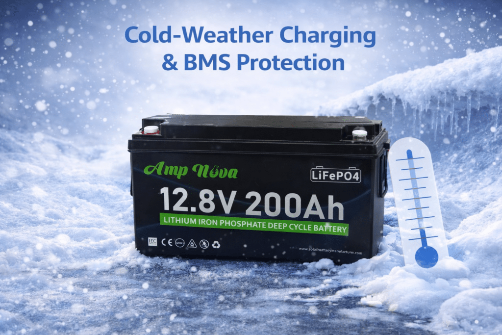
Safe Charging Temperature Range (Cold-Weather Charging & BMS Protection)
We receive many “battery won’t charge” tickets in winter, and most are not charger failures. The BMS is usually doing its job and blocking cold charging to protect the cells.
Most LiFePO4 batteries should be charged above 0°C (32°F) and below about 45°C (113°F), unless the battery is explicitly rated for colder charging. Charging below freezing can plate lithium and cause permanent damage, so many BMS units cut off charge current until the cells warm up.
Why cold charging is risky
Below freezing, the cell chemistry cannot accept charge normally. If you force it, you can cause lithium plating, which is a permanent damage mechanism. That is why BMS low-temp charge cutoffs exist.
What BMS protection looks like in the field
Common symptoms:
- Charger shows “on,” but current is near zero.
- Battery app/log shows “charge MOSFET off” or “low temp protect.”
- The system charges again later in the day when the enclosure warms.
Cold-weather charging playbook (simple and reliable)
- Warm the battery first.
- Use a battery heater pad with thermostat.
- Put batteries in an insulated enclosure.
- Charge later in the day.
- In solar, schedule heavy charging after the sun warms the enclosure.
- Reduce charge current in cold conditions.
- Even above 0°C, lower current can reduce stress.
- Avoid temperature compensation that increases voltage.
- Many controllers assume lead-acid behavior. Disable or neutralize temp comp for LFP.
- Watch condensation and connections.
- Cold metal + warm air can create moisture. Keep terminals clean and protected.
Hot-weather notes
High temperatures also matter:
- Heat accelerates aging.
- High current + high ambient temperature can push internal temps up.
If the enclosure is hot, consider:
- lower charge current,
- better airflow,
- shading for outdoor battery cabinets.
Safety note: Do not place heaters or batteries near flammables. Use proper fusing and wiring practices and follow local electrical codes.
Troubleshooting LiFePO4 Charging Issues (BMS Cutoff, Not Reaching Full, Overvoltage)
On our support bench, we solve most charging issues by doing three measurements in order: battery terminal voltage, charge current, and temperature. Then we match them to the charger settings.
When LiFePO4 charging fails, first confirm pack voltage (12/24/48V) and charger setpoints, then measure voltage at the battery terminals during charge. BMS cutoffs are commonly caused by low temperature, overvoltage from wrong profiles, or overcurrent. “Not full” problems often come from conservative voltages, short absorption time, or voltage drop in cables.
Fast diagnostic flow (5 minutes)
- Identify the pack: 12/24/48V and capacity (Ah).
- Read charger settings: absorption voltage, float voltage, absorption time, current limit.
- Measure at the battery terminals while charging:
- Voltage
- Current (clamp meter is ideal)
- Battery temperature (or BMS reported temp)
- Check the BMS status: any active protection flags?
- Inspect wiring: loose lugs, undersized cables, hot connectors, blown fuses.
Common problems and fixes (matrix)
| Symptom | Likely Cause | What to Measure | Fix |
|---|---|---|---|
| Charger shows charging, but 0A into battery | BMS low-temp cutoff | Battery/BMS temp | Warm battery; add heater; charge above 0°C |
| Charging stops near the top | Absorption voltage too high or equalize on | Terminal voltage at cutoff | Disable equalize; lower absorption voltage slightly |
| Battery never reaches “full” | Absorption voltage too low or absorption too short | Terminal voltage and taper current | Raise absorption within safe range; increase absorption time or tail-current logic |
| Charger reports full too early | Termination set by time too short | Absorption timer and current | Increase absorption time; use tail current if available |
| Overvoltage alarms | Wrong profile (lead-acid), alternator spikes, controller bug | Charger output waveform and peak V | Use LFP profile; add DC-DC charger; update firmware if applicable |
| Controller shows correct V, battery sees less | Voltage drop in wiring | V at controller vs V at battery | Increase cable size; shorten run; tighten/replace lugs |
| BMS trips on overcurrent | Charger current too high | Charge current at start of CC | Reduce current limit; use smaller charger or controller cap |
Mini decision tree (simple)
- If charge current is zero:
- Check joto → if below 0°C, warm the battery.
- If temperature is OK, check BMS flags and charger enable.
- If charge current is high but stops abruptly near full:
- Check if equalize/desulfate is enabled.
- Check absorption voltage vs recommended range.
- If it never hits full:
- Check battery terminal voltage under charge.
- If low, fix wiring drop or raise absorption within safe limits.
- If voltage is fine but SOC is low, check BMS calibration/app settings.
A note about “BMS reset”
Some BMS units require:
- removing the charger and loads for a short period,
- or pressing a physical reset,
- or using an app command.
Do not repeatedly “hammer” the battery with reconnect cycles. Fix the root cause (often temperature or wrong voltage settings).
Verify you are not mixing 12V/24V/48V settings
This is the second user insight, and it causes real damage:
- A 24V charger on a 12V pack will push voltage too high fast.
- A 12V charger on a 24V pack will never reach absorption.
Rule: Battery nominal voltage and charger nominal voltage must match. Then set absorption/float correctly.
Maswali Yanayoulizwa Mara kwa Mara
Can I charge a LiFePO4 battery with a lead-acid charger?
Sometimes it will “work,” but it is risky. Lead-acid chargers may run equalize or desulfation modes that can overvoltage an LFP pack and trip the BMS. Use an LFP profile charger or a configurable CC/CV charger with equalize disabled.
What is the best charging voltage for a 12V LiFePO4 battery?
Many 12V-class (4S) LiFePO4 packs charge around 14.2–14.6V in absorption, depending on the battery’s datasheet and balancing needs. Start conservative if you are unsure, then verify at the battery terminals during charging.
Should I float a LiFePO4 battery?
Often you can disable float for daily-cycled systems. If you need standby readiness (backup/UPS), use a low float setting recommended by the battery maker. Avoid keeping the battery at 100% for long periods if you want maximum long-term life.
How long does it take to charge LiFePO4?
Time depends on charge current and battery size. A rough estimate is: hours ≈ (Ah to replace) ÷ (charge amps), plus some extra time for CV taper. Higher current reduces time but can increase heat and stress.
Can I charge LiFePO4 in freezing weather?
Most LiFePO4 batteries should not be charged below 0°C unless the battery is specifically rated for it or has internal heating. Many BMS units block charging when cells are too cold. Warm the battery first.
Why does my battery stop charging near the top?
Common causes include absorption voltage set too high, equalize mode enabled, or the BMS protecting against cell overvoltage. Measure terminal voltage at cutoff and reduce absorption voltage slightly, and ensure equalize/desulfate are disabled.
Why does my LiFePO4 battery not reach 100% SOC?
SOC estimation can drift, and some chargers stop absorption too early. Confirm terminal voltage reaches the absorption setpoint and that current tapers. If needed, extend absorption slightly or enable a tail-current termination method.
Do I need a special charger for solar MPPT?
You need an MPPT controller that supports LiFePO4 settings or a custom profile. Program absorption/float and current limits correctly, and disable lead-acid-only features like equalization and temperature compensation that raises voltage.
Is fast charging (1C) bad for LiFePO4?
Not always, if the battery and BMS allow it and temperature is controlled. But for longer life, many systems charge at 0.2C–0.5C when time allows. Heat and high voltage time are the real enemies.
Hitimisho
Charge LiFePO4 with an LFP CC/CV profile, confirm pack voltage first, set conservative voltages and C-rate, and respect temperature limits. Next step: verify your settings with a meter at the battery terminals.