
What is bess?
In our QC bay, we often see teams oversimplify “storage” and then get hit by performance gaps and safety rework because the system is more than batteries. A BESS fixes that problem with engineered controls, protection, and thermal design.
A BESS (Battery Energy Storage System) stores electrical energy in rechargeable batteries and releases it later to support site loads, the grid, or renewable integration. It usually charges when electricity is abundant or cheap and discharges when demand is higher, during outages, or when grid services pay.
If you work in solar, EPC, or O&M, knowing the real building blocks and constraints helps you size, permit, commission, and operate BESS projects with fewer surprises.
Mini Table of Contents
- What Is a Battery Energy Storage System (BESS)?
- How Does a BESS Work?
- Key Components of a BESS
- Benefits and Advantages of BESS
- Common BESS Applications and Use Cases
- BESS Safety, Risks, and Regulations
What Is a Battery Energy Storage System (BESS)?
On our production line, the most common misunderstanding is calling a container of batteries “a BESS,” then discovering the project still needs inverters, controls, protections, and thermal management to function safely and predictably.
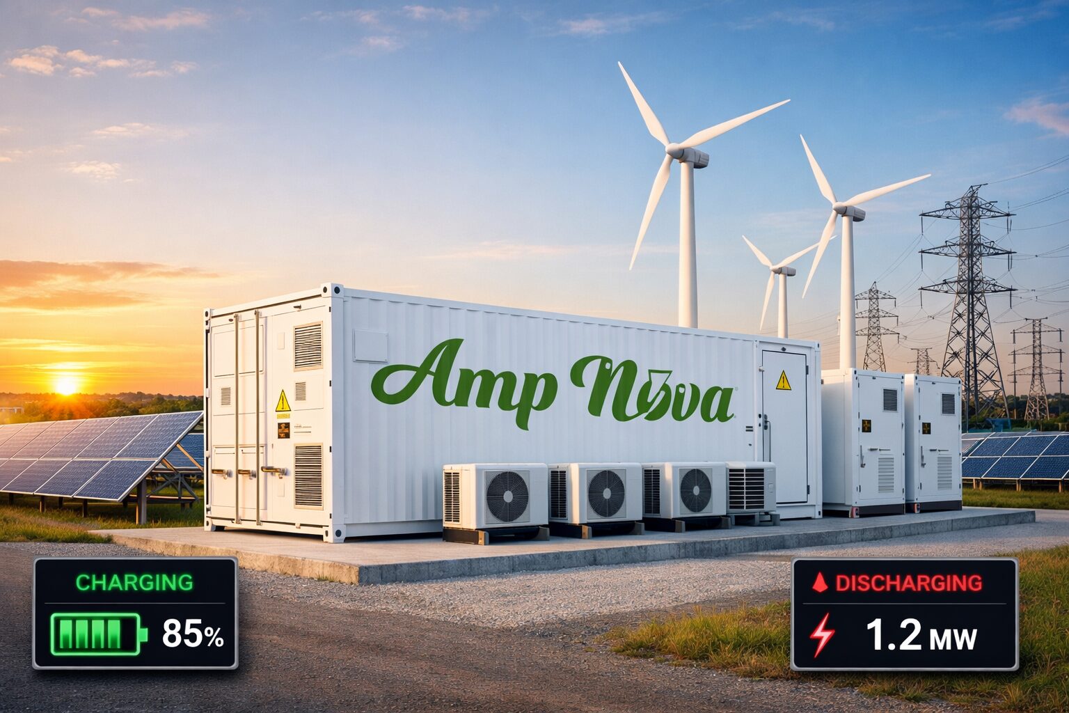
A Battery Energy Storage System (BESS) is an engineered system that stores electricity in rechargeable battery packs and delivers it later through power electronics and controls. In practice it is often a containerized, grid-connected asset that includes DC batteries, AC conversion, monitoring, thermal management, and safety protection.
The simplest definition that still works in the field
A BESS is not just energy capacity. It is a controlled power plant that can both absorb and inject power. That control is why BESS shows up everywhere from rooftops to utility substations.
At minimum, a BESS does three things:
- Stores energy (DC) in batteries.
- Converts power (DC↔AC) to match the load or grid.
- Controls dispatch so power goes out at the right time, at the right rate, under safe limits.
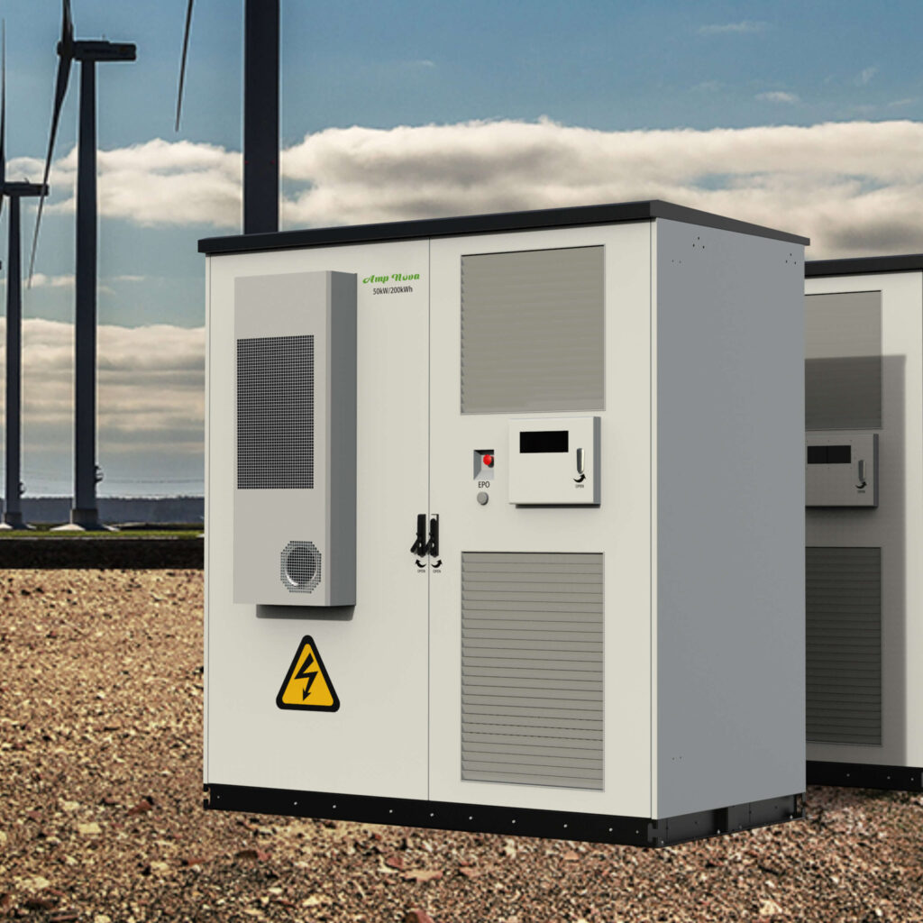
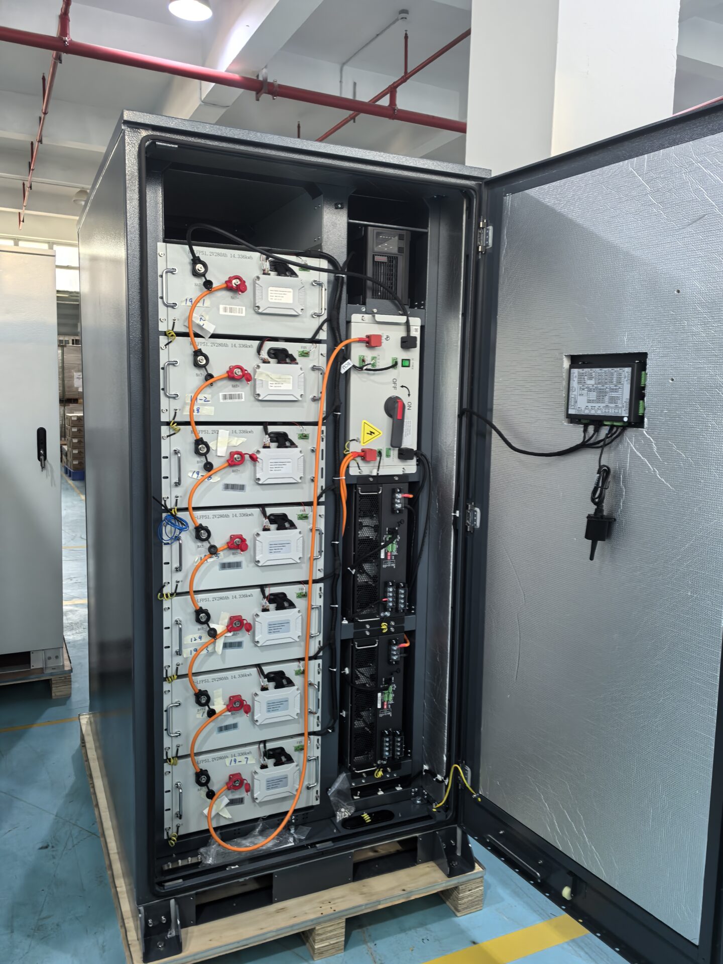
Containerized BESS vs. “battery bank”
Your personal view is the one we also see most in commercial projects: BESS is often large-scale, containerized storage. Inside the enclosure you typically have:
- DC side: battery racks/modules, DC cabling, fusing/contactors, DC disconnects.
- AC side: PCS (bi-directional inverter) output, AC switchgear, protection relays.
- Controls: EMS, communications, metering, logging.
- Thermal: HVAC or liquid cooling, sensors, alarms.
- Safety: gas/smoke detection, suppression strategy, emergency stop, ventilation paths.
That is why two projects with the same “MWh” can perform very differently. The balance-of-system design decides ramp rate, availability, and safety outcomes.
How people size BESS in plain terms
Most buyers think in two numbers:
- Power (kW/MW): how fast the BESS can charge/discharge.
- Energy (kWh/MWh): how long it can run at that power.
A common market pattern is ~1–4 hours of rated duration (for example, a 1 MW / 2 MWh system is “2-hour”). This is not a rule of physics. It is a design choice driven by revenue streams, interconnection limits, and battery cost.
Table: BESS terms that prevent scope mistakes
| Term | What it means | Why it matters in contracts |
|---|---|---|
| kW / MW (Power) | Instant output/input capability | Defines inverter/PCS and interconnection limits |
| kWh / MWh (Energy) | Stored energy capacity | Defines duration and battery count |
| Duration (hours) | Energy ÷ Power at rated output | Ties directly to use case (peak shaving vs backup) |
| Round-trip efficiency | Energy out ÷ energy in | Impacts operating cost and modeled savings |
| SOC window | Allowed state-of-charge range | Drives degradation and usable energy |
| C-rate | Charge/discharge rate vs capacity | Higher C-rate increases heat and wear |
| Availability | Time system is ready to operate | Often ties to liquidated damages |
How Does a BESS Work?
In our commissioning reports, most early failures come from control handoffs: the batteries are fine, but the charge/discharge logic fights site limits or utility requirements and trips protection.
A BESS works by charging batteries when energy is available or cheap and discharging later when demand is higher, power is unavailable, or grid services are valuable. A controller keeps the system within limits for SOC, temperature, voltage, and current while coordinating the PCS to exchange AC power with the site or grid.
The charge–store–discharge loop
A practical BESS loop looks like this:
Sense
- Meters read site load, PV output, grid import/export, frequency/voltage.
- Battery sensors read cell/module voltages, temperatures, and currents.
Decide
- EMS selects a target: charge, discharge, idle, or provide a service.
- Constraints apply: SOC limits, export limits, demand caps, fire-code modes, utility signals.
Act
- PCS ramps power to the setpoint.
- BMS validates battery conditions and allows contactors to stay closed.
Protect
- If any limit is exceeded, the system reduces power or trips safely.
This is why BESS is known for very fast response. Many systems can ramp extremely quickly (often described as sub-second response) because power electronics can change output far faster than mechanical generators.
Why “cheap vs expensive” charging is only the start
Yes, many BESS projects charge on surplus solar/wind or off-peak tariffs and discharge on peaks. But real projects add more rules, such as:
- Demand charge caps: never exceed a site kW limit.
- Export restrictions: do not backfeed beyond interconnection permission.
- Reserve SOC: keep energy for outage ride-through.
- Temperature rules: reduce power when cooling cannot hold setpoint.
- Degradation rules: avoid deep cycles if revenue is low.
Dispatch strategies that respect degradation
The “real” economics are often dominated by battery degradation. So dispatch is no longer “maximize revenue today.” It is “maximize revenue over life.”
A field-ready decision rule we use in controls reviews:
- If the value of the discharge is lower than the estimated wear cost, do not cycle.
- If temperature is high, reduce C-rate or narrow the SOC window.
You can model wear cost simply with an internal score (not a lab-accurate model, but good enough to prevent bad dispatch):
- Assign “wear points” per kWh based on depth of discharge, C-rate, and temperature.
- Dispatch only when revenue per kWh exceeds wear cost per kWh plus losses.
Table: Common operating modes and what triggers them
| Mode | Trigger | What the system does | Common pitfall |
|---|---|---|---|
| Load shifting | TOU price spread | Charge off-peak, discharge on-peak | Cycles too deeply and accelerates fade |
| Peak shaving | Demand limit | Discharge when load nears threshold | Meter placement errors cause missed peaks |
| PV self-consumption | Export limit / low FIT | Store midday PV, discharge later | SOC fills too early, curtails PV anyway |
| Backup reserve | Critical load requirement | Hold SOC, discharge on outage | Reserve too large, reduces daily value |
| Grid services | Utility/aggregator signal | Fast regulation or voltage support | Interconnection/telemetry not accepted |
Key Components of a BESS
When we do incoming inspection, we treat BESS as five systems that must agree with each other: energy (cells), safety (BMS), conversion (PCS), brain (EMS), and environment (thermal + monitoring). Weakness in one breaks the whole.
Most BESS designs use the same core building blocks: battery cells assembled into modules and racks, a Battery Management System (BMS) for protection and balancing, a Power Conversion System (PCS/inverter) for AC coupling, an Energy Management System (EMS) for dispatch, and thermal plus monitoring subsystems for safe, reliable operation.
Battery cells, modules, racks, and strings (DC energy block)
- Cells store energy chemically.
- Cells group into modules.
- Modules install into racks.
- Racks connect into strings and then a DC bus.
What matters in the field is not chemistry marketing. It is:
- Consistent module assembly
- Stable interconnect resistance
- Clear torque specs and labeling
- Robust isolation and grounding strategy
BMS (Battery Management System)
BMS is the battery’s safety controller. It typically:
- Measures cell/module voltage and temperature
- Balances cells
- Estimates SOC and SOH (state of health)
- Enforces limits (over/under-voltage, overcurrent, over-temperature)
- Commands contactors open/close, often with pre-charge control
If the BMS is conservative, you get lower usable energy but higher safety margin. If it is aggressive, you may get more capacity but higher risk and faster wear.
PCS (Power Conversion System / bi-directional inverter)
PCS converts between DC battery power and AC grid/load power. It also:
- Controls power factor and reactive power (if enabled)
- Ramps quickly for grid services
- Synchronizes to grid voltage/frequency
- Trips on abnormal conditions per protection settings
PCS capability often sets real limits on:
- Peak shaving response
- Frequency regulation speed
- Harmonic performance and compliance
- Islanding behavior for backup systems
EMS (Energy Management System)
EMS is the dispatch “brain.” It may run on-site or in the cloud. It typically:
- Reads tariffs, demand limits, PV forecasts
- Receives grid service setpoints
- Decides charge/discharge schedule
- Coordinates PCS and respects BMS constraints
- Logs events for diagnostics and revenue settlement
Thermal management and monitoring subsystems
Thermal systems are not optional. Temperature drives:
- Power derating
- Degradation rate
- Safety risk
Monitoring includes:
- Sensors (temperature, humidity, smoke/gas where used)
- Alarms and event logs
- Remote access (with cybersecurity controls)
- CCTV in some sites (policy dependent)
Protection, switchgear, and “all the boring parts”
BESS needs safe isolation and coordination:
- DC fuses, contactors, disconnects
- AC breakers, relays, transformers (if needed)
- Surge protection, grounding, insulation monitoring
- Emergency stop circuits
These parts decide whether commissioning is smooth or painful.
Table: Component → failure mode → how to catch it early
| Component | Common failure mode | Early detection method | Practical fix |
|---|---|---|---|
| Battery racks | Loose busbar/terminal heating | IR scan under load, torque audit | Retorque, replace damaged lugs |
| BMS | Nuisance trips from sensor drift | Compare sensor trends, sanity checks | Calibrate/replace sensors, adjust thresholds carefully |
| PCS | Trips on grid events | Event logs + waveform capture | Tune protection with utility, improve ride-through settings |
| EMS | Wrong dispatch due to bad meter data | Meter validation, cross-check bills | Fix CT orientation, update scaling, lock configs |
| HVAC/cooling | Hot spots, uneven temps | Temperature map across racks | Balance airflow, maintain filters, service compressors |
| Comms/network | Intermittent control loss | Ping/latency logs, packet captures | Segmentation, QoS, redundant links where needed |
Benefits and Advantages of BESS
In our field tests, the biggest disappointment happens when teams promise “huge savings” but ignore constraints like interconnection limits, demand profile shape, and degradation. The best projects match one clear value stream first, then add others.
BESS delivers value by shifting energy across time and stabilizing power quickly. It can reduce peak demand charges, provide backup power, smooth solar and wind variability, and support the grid with fast services like frequency regulation and local voltage support, often responding in fractions of a second.
Benefit 1: Peak shaving and load shifting
- Peak shaving reduces the maximum kW your site pulls from the grid.
- Load shifting moves energy use to cheaper periods.
A simple sizing method for peak shaving:
- Plot 15-minute (or utility interval) demand data.
- Choose a target demand cap.
- Compute how many kW you must shave during peaks.
- Estimate duration of those peaks to get kWh.
Reality check:
- If peaks are short and sharp, you need high power.
- If peaks are long, you need more energy.
- If both, costs rise quickly.
Benefit 2: Backup and resilience
For critical loads, BESS can:
- Ride through short outages instantly
- Support black-start sequences (if designed for it)
- Reduce generator runtime and fuel
But backup design needs careful boundary definition:
- What loads are “critical”?
- How many hours are required?
- Is islanding allowed by local codes and the utility?
Benefit 3: Renewable smoothing and curtailment reduction
BESS helps PV by:
- Storing midday surplus instead of curtailing
- Firming output ramps from cloud events
- Meeting export limits while maximizing self-consumption
A practical note: PV smoothing often requires fast power response more than large energy.
Benefit 4: Grid services (fast response value)
Many overviews emphasize BESS for:
- Frequency regulation
- Voltage support
- Fast response ancillary services
BESS can react quickly because PCS can change power output fast. Whether you get paid depends on the market and telemetry requirements.
Benefit 5: Better utilization of interconnection
Sometimes the bottleneck is not the PV array. It is the interconnection export limit. BESS can:
- Store energy behind the meter
- Shape export to comply with limits
- Increase effective utilization of PV and site load
The economics you cannot ignore: degradation dominates
Battery life is strongly influenced by:
- Depth of discharge (DoD)
- Charge/discharge rate (C-rate)
- Temperature
- Time at high SOC
So the best projects align control strategy with warranty and expected duty cycle.
A simple “dispatch sanity checklist” we use:
- Avoid unnecessary cycling for small price spreads.
- Keep temperatures stable.
- Use conservative SOC windows if revenue does not justify wear.
- Log every cycle and track capacity trend monthly.
Table: Benefits vs. what you must verify before promising ROI
| Benefit claimed | What to verify | What usually breaks the model |
|---|---|---|
| Demand savings | Interval data, tariff structure, ratchets | Peaks driven by rare events you cannot shave |
| Energy arbitrage | Real TOU spread, losses, cycle limits | Spread too small after efficiency + wear cost |
| Backup | Critical load list, islanding design, ATS | Utility does not allow islanding as assumed |
| PV curtailment reduction | Export limit, PV profile, SOC headroom | Battery fills early; curtailment still happens |
| Grid services revenue | Market rules, telemetry, performance tests | Interconnection/qualification delays |
Common BESS Applications and Use Cases
On the applications side, we see teams pick a use case based on a brochure, then get stuck in interconnection and permitting. The best approach is to pick a “primary” use case and treat others as optional add-ons.
Common BESS applications include commercial peak shaving and load shifting, solar self-consumption and ramp smoothing, backup power for critical facilities, and grid services such as frequency regulation and local voltage support. Many systems are sized around 1–4 hours of duration because that matches typical peak periods and market products.
1) Commercial & industrial: demand charge management
Typical sites:
- Factories, warehouses, data-adjacent facilities, cold storage, campuses
What makes it work:
- Predictable peaks
- Control integration with building management systems
- Accurate metering and demand forecasting
Commissioning tips:
- Validate CT/PT orientation and scaling.
- Compare EMS demand values against utility meters.
- Test peak events with controlled loads if possible.
2) Solar + storage (behind the meter): self-consumption and export control
Use cases:
- Reduce export when feed-in tariffs are low
- Avoid export violations
- Increase PV utilization
Decision rule:
- If export is limited, prioritize “headroom management” so SOC is not full at noon.
3) Microgrids and resilience for critical loads
Typical sites:
- Hospitals, telecom, water treatment, ports, industrial processes
Key design questions:
- Does the site need seamless transfer (no break)?
- How long must it run without grid?
- Will there be generators, and how will they share load?
This is where controls matter most. Poor governor settings or unstable PCS/generator interaction can cause oscillations and trips.
4) Utility-scale: energy shifting and grid support
Utility projects often target:
- Peak capacity support
- Congestion relief
- Ancillary services
Here, a major constraint is often interconnection and queue timelines:
- Studies can take a long time.
- Grid upgrades can be required.
- Permitting and fire-code constraints can change layout.
5) Fast-response services: frequency regulation and power quality
If you need speed, BESS is a strong tool:
- Fast ramp response
- Precise control
- Repeatable performance
But qualification may require:
- Specific telemetry
- Accuracy tests
- Availability commitments
Timeline reality: interconnection and permitting can dominate
Many projects are constrained less by battery price and more by:
- Utility queue delays
- Site-specific upgrades
- Fire-code spacing, access lanes, ventilation rules
- Local authority requirements
So feasibility should run in parallel:
- Electrical single-line and protection study
- Fire code concept layout
- Interconnection pre-app discussion (where possible)
- Noise, drainage, and access planning (for container sites)
Table: Use case → best-fit sizing logic (quick guide)
| Use case | Primary sizing driver | Typical duration logic | Control priority |
|---|---|---|---|
| Peak shaving | kW shaved at peak | Match peak length | Demand forecast accuracy |
| PV self-consumption | PV surplus profile | Cover evening shoulder | SOC headroom at noon |
| Backup | Critical load kW | Required autonomy hours | Islanding stability, reserves |
| Grid services | Market product requirements | Often shorter energy | Response speed and telemetry |
| Utility shifting | Peak capacity need | Often 2–4 hours | Availability and dispatch optimization |
BESS Safety, Risks, and Regulations
In our safety reviews, the biggest risk is assuming “battery = safe if enclosed.” A BESS concentrates energy and requires layered protection. If teams ignore standards early, they pay later in redesign, spacing changes, and permit delays.
BESS safety focuses on preventing and containing thermal runaway and managing fire, gas, and electrical hazards through tested equipment, protective controls, and compliant installation. Common references include UL 9540 system listing, UL 9540A thermal-runaway propagation testing, and NFPA 855 installation requirements, alongside local fire and electrical codes.
The core hazards (plain language)
Thermal runaway and fire propagation
- A cell failure can heat neighbors.
- Gases can vent and ignite.
- Heat can damage wiring and controls.
Electrical hazards
- High DC voltage and fault current.
- Arc flash on AC switchgear.
- Ground faults and insulation breakdown.
Toxic/flammable gas
- Venting during failures can create hazardous atmospheres.
- Ventilation strategy matters.
Thermal management failure
- Cooling loss can cause derating and accelerated degradation.
- Persistent hot spots increase risk.
Control and cybersecurity risk
- EMS/PCS are often network-connected.
- Unauthorized access can cause unsafe dispatch or outages.
Standards and what they mean in project terms
- UL 9540: System-level safety listing for energy storage systems (how the complete system is evaluated).
- UL 9540A: Test method focused on thermal runaway propagation characteristics (used to inform installation and mitigation).
- NFPA 855: Installation standard addressing spacing, fire protection, and related safety considerations.
You still must check local codes and the Authority Having Jurisdiction (AHJ). Local fire departments and electrical inspectors can add requirements beyond baseline standards.
Practical safety design layers we look for
Layer 1: Prevention
- Conservative BMS limits
- Quality assembly and torque control
- Thermal uniformity (no persistent hot spots)
Layer 2: Detection
- Temperature sensing and alarming
- Smoke/gas detection where applicable
- Continuous monitoring with event logs
Layer 3: Isolation
- Contactors and breakers that open reliably
- Clear emergency stop behavior
- DC and AC disconnect access
Layer 4: Mitigation
- Venting paths and pressure relief design
- Fire suppression strategy aligned to enclosure design
- Site layout that supports access and separation
Cybersecurity: treat it like safety
Because EMS and PCS are often connected for monitoring and market participation, cybersecurity is now a core risk area.
Practical controls that work:
- Network segmentation (BESS controls on their own VLAN/subnet)
- Authenticated control (no shared passwords, no open ports)
- Least privilege (roles for operators vs installers)
- Logging and monitoring (alerts for abnormal access)
- Patch policy (planned maintenance windows, tested updates)
A simple site rule:
- If remote access exists, it must be documented, audited, and revocable.
End-of-life (EOL) planning reduces stranded-asset risk
Bankable projects increasingly include:
- Repowering plan (module swaps when capacity drops)
- Contracted recycling pathway
- Clear chain-of-custody and liability
- Hazardous materials handling procedures
If you do not plan EOL, you may face:
- Unexpected disposal cost
- Permit complications
- Decommissioning delays
- Insurance and lender concerns
A field-ready safety checklist for project teams
- Confirm which standards apply (and which are required by AHJ).
- Lock the site layout early (spacing, access, ventilation, egress).
- Define emergency procedures with the site owner and local responders.
- Validate protection settings with utility interconnection requirements.
- Commission thermal management at worst-case ambient assumptions.
- Implement cybersecurity controls before first remote login.
- Set up lifecycle monitoring: capacity trend, temperature trend, cycle counting.
FAQ
1) What does BESS stand for?
BESS stands for Battery Energy Storage System. It is a complete system that stores electricity in batteries and delivers it later through power electronics, controls, and safety subsystems.
2) Is a BESS the same as a UPS?
Not exactly. A UPS is typically designed for short-duration, immediate backup and power conditioning. A BESS can provide UPS-like behavior, but it is often designed for longer-duration dispatch, grid interaction, and revenue-generating services.
3) Why are many BESS projects “1–4 hours”?
Because many peak periods and market products fit that duration range. It is a common design choice that balances battery cost, revenue opportunities, and interconnection constraints, but it is not a universal rule.
4) What are the main parts inside a containerized BESS?
Commonly: battery racks/modules on the DC side, BMS, PCS/inverter for AC output, EMS controls, thermal management (HVAC or liquid cooling), monitoring, and protective switchgear and disconnects.
5) How fast can a BESS respond?
Power electronics can change output very quickly, and sub-second response is commonly cited for many grid-support functions. Actual performance depends on PCS controls, interconnection settings, and protection coordination.
6) What drives BESS degradation the most?
Depth of discharge, charge/discharge rate (C-rate), temperature, and time spent at high state-of-charge are major drivers. Dispatch strategy should balance revenue with lifetime wear.
7) What standards are commonly referenced for BESS safety?
Many projects reference UL 9540, UL 9540A, and NFPA 855, plus local electrical and fire codes. Your AHJ and utility requirements can add project-specific conditions.
8) Why do BESS projects get delayed even when hardware is available?
Interconnection studies, queue timelines, permitting, and required grid upgrades often take longer than expected. Site layout constraints from fire code and access requirements can also force redesigns.
9) Does a BESS introduce cybersecurity risk?
Yes. EMS and PCS are often network-connected for monitoring and control. Segmentation, authentication, logging, and a patch policy reduce risk significantly, especially for critical facilities.
10) What happens at the end of life for a BESS?
Projects increasingly plan for repowering (module swaps) and recycling with clear chain-of-custody and liability. Early EOL planning reduces stranded-asset risk and avoids expensive disposal surprises.
Conclusion
BESS is more than batteries. It is a controlled, protected, and cooled power system. Define the use case, design for safety and degradation, and confirm interconnection and permits early.